Table of Contents
OFDM 500F
| 
OFDM 750F
|
OFDM 2000F
| 
OFDM 2000
|
Microphone Jack Modes
These modes can be used with almost any SSB or FM transceiver unmodified, and with any SignalLink soundcard interface (either with the old or new transformers).
| Name | Usage | BW Hz | Baud | Carriers | Mod' | Bit/Sec | Datarate | FEC |
|---|---|---|---|---|---|---|---|---|
| OFDM 500F | SSB | 500 | 62.5 | 4 | 4PSK | 500 | 250 | K=15 @ 1/2 rate |
| OFDM 750F | SSB | 750 | 125 | 3 | 8PSK | 1125 | 562 | K=13 @ 1/2 rate |
| OFDM 1250F | SSB | 1250 | 125 | 5 | 8PSK | 1875 | 937 | K=13 @ 1/2 rate |
| OFDM 2000F | SSB/FM | 2000 | 125 | 8 | 8PSK | 3000 | 2000 | K=11 @ 2/3 rate |
| OFDM 2000 | SSB/FM | 2000 | 250 | 4 | 8PSK | 3000 | 3000 | NONE |
- OFDM 500F /750F are intended for NVIS and regular HF-skip usage.
- OFDM 2000F is intended for HF skip, and through FM-repeaters.
- OFDM 2000 is intended for line-of-sight HF/VHF/UHF SSB.
- The OFDM 500F and 750F modes are tx/rx frequency-agile modes.
- Modes OFDM 2000, and 2000F are transmit-frequency locked (rx agile only).
9600 Port Modes
These modes can be used with almost any 9600-capable FM transceiver unmodified.
| Name | Usage | BW Hz | Baud | Carriers | Mod' | Bit/Sec | Datarate | FEC |
|---|---|---|---|---|---|---|---|---|
| OFDM 3500 | FM 9600-port | 3500 | 250 | 7 | 8 PSK | 5,250 | 5,250 | NONE |
| OFDM 6000 | FM 9600-port | 6000 | 250 | 12 | 8 PSK | 9,000 | 9,000 | NONE |
| OFDM 7000 | FM 9600-port | 7000 | 250 | 14 | 16 QAM | 14,000 | 14,000 | NONE |
- OFDM 3500 requires a SignalLink soundcard interface that has the new transformers (built after June 2018). To use this mode, the soundcard interface must be connected to the radio's 9600-port (set JP4 on SignalLink).
- DRA adapters from Masters Communications (or similar) are used for modes OFDM 3500, 6000, and 7000.
- The mode OFDM 3500 is intended for VHF/UHF line of sight communications.
- The OFDM 3500 signal is far too wide to operate through FM repeaters.
Use of the radio's 9600-port bypasses the pre-emphasis, de-emphasis, and audio-bandpass filters giving far less distortions and a wider usable bandwidth.
Performance
OFDM 500F
This mode can survive with 100% decode the "Mid-Latitude Disturbed NVIS" simulation, including multiple 2 second deep-fades causing complete-losses of reception. Simulation results confirmed by real-world testing.
OFDM 750F
This mode can survive with 100% decode the "Mid-Latitude Disturbed NVIS" simulation including multiple 1.5 second deep-fades causing complete-losses of reception. Simulation results confirmed by real-world testing.
Other Modes
Currently in Testing.
UTF-8 Support
The OFDM modes support sending all UTF-8 characters. This means the mode can be used to communicate in any language. Please ensure the font chosen in Fldigi has the characters for the language you are trying to use, otherwise Fldigi will just display every character as an empty box.
RSID Usage
OFDM modes require a high-degree of frequency accuracy to operate. This is achieved by utilizing RSID to set the receive frequency to ± 3Hz. RSID is mandatory for the OFDM 500F, OFDM 750F, and OFDM 2000F modes.
When received, the RSID triggers the receiver end to flush the long interleaver and soft-decision viterbi decoder. This prepares the viterbi decoder and interleaver for the data about to be received and is required for the long 3200 millisecond interleaver.
Flushing any received noise-bits before decoding the actual signal decreases the probability of error and provides FEC gain. This gain comes from not mixing the good data-bits with bad noise-bits by pre-filling interleaver and soft-decoder instead with punctures.
Technical Details
Vestigial AFC
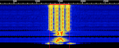
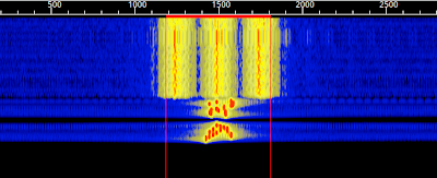
OFDM sends a continuous-phase & continuous-frequency tone slightly lower in frequency than the data-signal. This tone is used to provide an accurate frequency/phase reference, allowing for denser PSK modulations on HF.
This vestigial tone is used for Automatic Frequency Control, after RSID.
Vestigial AFC improves decode by:
- Compensating for frequency drift, common with older radios
- Providing a stable AFC frequency reference: +- 0.5 Hz accuracy
- Automatically adjusting for mobile doppler-shifts (up to around 900Mhz)
- Adjusting for +- 5Hz instantaneous shifts mid-transmission
- Allowing for drift-rates of up to 1Hz/second (60Hz/minute)
- Maintaining receive orthogonality by keeping the center-frequency highly accurate.
Forward Error Correction
The forward error correction used by the OFDM modes are inspired by the longer constraint length codes used by NASA for deep-space communications.
Only in recent years have home computers become powerful enough to run these FEC algorithms realtime.
The long-codes provide extra FEC power needed to handle normal HF noise combined with NVIS-distortions or deep-fades.
Use of soft-decision Viterbi FEC and long-tracebacks help the OFDM FEC provide additional coding gain, allowing the modes work well even with highly-distorted signals and multiple complete losses of signal.
-
OFDM 500F
- A constraint length 15 convolutional FEC is used at 1/2 rate. This gives a free distance of 18 (can correct a 8-bit error). FEC achieves up to 8.6dB in coding gain (equivalent to using 7.2X more transmitter power)
-
OFDM 750F
- A constraint length 13 convolutional FEC is used at 1/2 rate. This gives a free distance of 16 (can correct a 7-bit error). This provides up to 7.8dB in coding gain (equivalent to using 6X more transmitter power)
-
OFDM 2000F
- A constraint length 11 convolutional FEC is used at 2/3 rate. This gives a free distance of 9 (can correct a 4-bit error). This provides up to ?.?dB in coding gain (equivalent to using ?X more transmitter power)
A traceback of 10 times the constraint length is used for modes 500F and 750F (un-punctured). This is increased to 14-times the constraint length for 2000F (punctured).
The 8-bit K=15 FEC is used for 500F because the datarate is low enough to ensure low CPU usage.
The 7-bit K=13 FEC is used for 750F simply to keep the CPU usage low at these faster datarates.
The 4-bit K=11 FEC is used for 2000F simply to keep the CPU usage low at these faster datarates.
Long Interleaving
The OFDM interleaver length has been modeled after MT63 and tailored for multicast-usage. This allows for a high level of robustness to fades at the expense of having a quite long turnaround time.
For NBEMS usage, where transmit times are many seconds long, a long interleaver gives coding-gain without negatively impacting throughput.
| Mode | Bits | msec | Survives fade of |
|---|---|---|---|
| OFDM 500F | 2000 | 4000 | < 2000 msec |
| OFDM 750F | 3600 | 3200 | < 1600 msec |
| OFDM 1250F | ???? | 2400 | < 1200 msec |
| OFDM 2000F | 4800 | 1600 | < 800 msec |
Using interleavers this long provides additional coding-gain, but also requires the longer constraint length FEC in order to function properly.
This is due to the FEC having to handle both normal HF noise in addition to correcting over fades of up to 2-seconds from NVIS.
For OFDM-2000F the interleaver length is moderately-sized for the HF bands, and meant for moderate to good channels.
This allows for a better hybrid digital-mode robust enough for strong HF signals, but without excessive delays on VHF/UHF.
The OFDM FEC modes are NOT meant to be used with any stop-and-wait protocols, like AX.25 or PSKmail. Stop-and-wait protocols will timeout if trying to use with an OFDM FEC mode.
Intercarrier Spacing
For OFDM-500F and OFDM-750F each subcarrier is spaced to twice minimum orthogonality. This reduces inter-carrier-interference making the modes usable at the signal to low-to-medium signal-to-noise ratios common of the amateur HF bands. Increased intercarrier spacing also increases the modes resistance to HF doppler-spread.
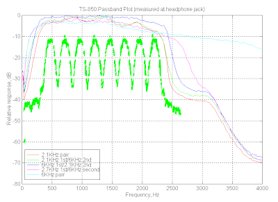
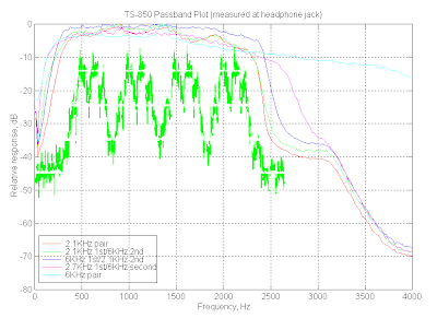
Pulse Shaping
Raised-cosine pulse-shaping is used on each symbol within each OFDM subcarrier.
This reduces the sidelobes of each carrier, which reduces inter-carrier-interference (ICI). By lowering ICI, these modes become more sensitive and usable at lower signal to noise ratios.
Pulse-shaping also decreases Inter-Symbol Interference (ISI) within the same carrier. The point of zero-amplitude provided by this pulse shaping serves as a reference to recover accurate signal timing.
Due to the low baudrates used, the zero-points of the pulse-shaping also acts as a minimally effective guard interval.
Timing Recovery
Since each symbol is raised-cosine pulse-shaped, there is a tiny moment of silence between each symbol. This silence is used for timing-recovery on the receiving side.
The low baudrates used allow the intersymbol zero-amplitude moments to be long enough the be detected and used for accurate timing-recovery.
Even with a constant string of 1's or 0's accurate timing synchronization is maintained.
Side Lobes
The orthogonal stacking of carriers to create an OFDM based mode causes multiple sidelobes, with only the sidelobes closest to the fundamental signal being significant.
The first side lobe is below the fundamental signal by -18dB and the second side lobe by -22dB.
The side lobes only become an issue at higher power-levels of ~500 watts and above.
Below this power-level, the sidelobes are likely at or below the noise floor for HF.
| Mode | Width | @ 25 watts | @ 250 watts | @ 500 watts | @ 1500 watts |
|---|---|---|---|---|---|
| OFDM-500F | 62.5 Hz | 0.0016 watts/Hz | 0.016 watts/Hz | 0.032 watts/Hz | 0.096 watts/Hz |
| OFDM-750F | 125 Hz | 0.0008 watts/Hz | 0.008 watts/Hz | 0.016 watts/Hz | 0.064 watts/Hz |
| OFDM-1250F | 62.5 Hz | 0.0013 watts/Hz | 0.013 watts/Hz | 0.026 watts/Hz | 0.080 watts/Hz |
| OFDM-2000F | 125 Hz | 0.0004 watts/Hz | 0.004 watts/Hz | 0.008 watts/Hz | 0.024 watts/Hz |
| OFDM-2000 | 250 Hz | 0.0004 watts/Hz | 0.004 watts/Hz | 0.008 watts/Hz | 0.024 watts/Hz |