Table of Contents
Receive audio
Setting the correct hardware, operating system, and fldigi received audio levels is not difficult, but it is the one setup procedure most often done incorrectly. The most commonly used sound card devices contain either a 16 or 24 bit analog to digital (a/d) converter. A 16 bit a/d can provide approximately 90 db of signal conversion. For the 16 bit converter, if the peak audio signal that the a/d can handle is +/- 1 volt then the minimum discernable signal (1 bit) will be +/- 30.5 microvolts. If more than a +/- 1 volt signal is applied to the a/d input then either one of two things may occur, (1) the audio is clipped, or (2) the audio is wrapped, large positive signals wrap to large negative signals and vice versa.
Signal decoding and signal display are two separate software processing paths:
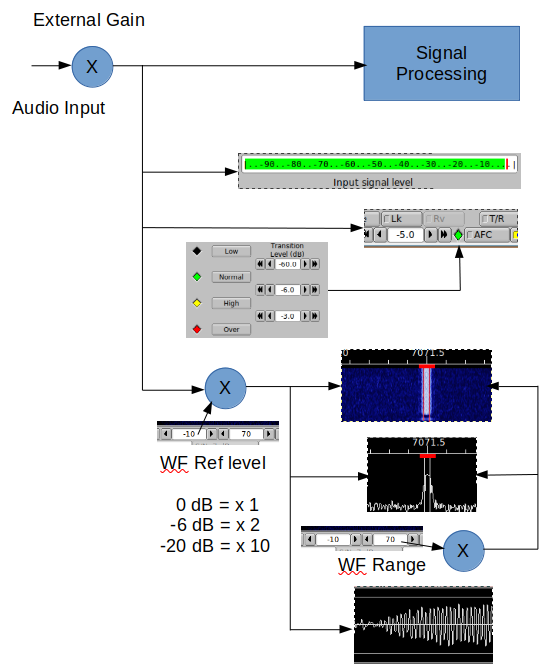
The objective in adjusting the Rx audio is to use the full dynamic range of the a/d without either incurring over or under drive. fldigi provides a number of display controls to assist in setting up the Rx audio. fldigi does not attempt to control the system input mixer controls. Those must be adjusted by the operator. Mixer control access is different for each of the supported operating systems. The input signal level effects the decoder performance and the visual presentation of the signal.
fldigi displays the raw input signal in a VU style meter. This meter is accessed from one of two signal level configuration panels:
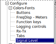
| 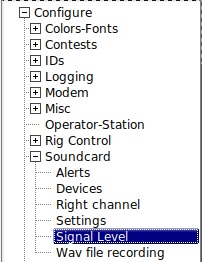
| 
|
and on the Main Dialog, location shared with center status bar control. Left click on the status bar / vumeter to toggle between the two.
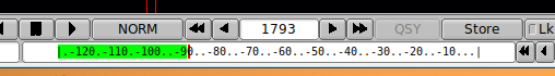
There are two controls that adjust the visual appearance of the waterfall. These controls are below and to the left of the waterfall, "Upper signal level (dB)", and "Signal range (dB)". The "Upper signal level" control is a gain control. 0 dB == x1,-6 dB = x2. These values are dB relative to input signal level. This control will effect the Waterfall (WF), Fourier Transform (FFT), and Signal (SIG) views. The "Signal range" control will only effect the WF and FFT views.
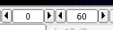
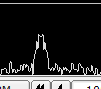
Set the level to -20 and the range to 70. Change the waterfall display to the "Scope" view.
Do this by pressing the "WF" button twice if it is currently displaying the waterfall. You can also right click once on that button. That button acts as a rotary and is left/right click sensitive. The display should show what looks like an oscilloscope view of the received audio. This is the entire audio signal and not just the signal that is currently decoded.
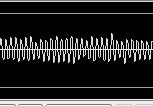
If your sound card a/d (also referred to as codec) is functioning correctly there should be no signal offset and the signal will be centered vertically about the x-axis. Set your transceiver to a portion of the band with no signals; 14.065 MHz might suffice. Adjust the audio path gain; transceiver audio, external audio codec gain, and operating system gain for a noise level that is about -50 dB on the VU meter. Then set the transceiver to an active portion of the digital band; 14.070 MHz for PSK or 14.074 MHz for JT type digital signals. Make sure that the input gain controls are not set too hot. The peak signals do should not exceed the upper/lower gray lines on the display. The diamond indicator to the left of the fldigi AFC button will be colored as follows:
- BLACK - no signal present
- GREEN - signals are in the correct range
- YELLOW - signals level high, but still OK
- RED - signals too high, danger of decode errors
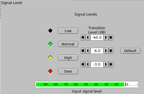
The transition levels can be adjusted on the "Signal Level" configuration panel. The default settings will be good for most users. The colors can be set to suit the users' color vision.
You can then proceed to adjust the waterfall/fft appearance when you have the audio Rx level adjusted correctly. Remember that changing the WF/FFT/SIG level and range controls DOES NOT effect the decoder signal path.
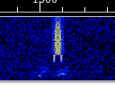
The three signal views should be similar to this with the level/range controls set to -20 and 70 respectively. The waterfall palette used is "default.pal", and the received signal is about 20 dB above the noise floor.
Windows Audio Properties
A combination of the Windows operating system and certain audio codecs needs to be accommodated. The codecs used by devices like the SignaLink-USB, the TS590S, and recent Icom transceivers are identified by the Windows operating system as "microphone" devices. The Windows mixer controls for that device are then set to insert about 30 dB of gain in the signal path. To compensate most users simply lower the transceiver audio output. The result is very poor decoding. The correct procedure is to force the Windows mixer controls to remove that 30 dB of gain. This procedure is for Windows 10, but is similar on Windows 7, and Windows 8.
Right click on the task bar speaker icon and select the "Recording devices" menu item. This will open the Sound devices dialog:
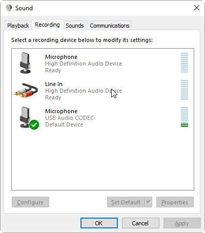
This is the dialog on my Windows 10 test computer with a SignaLink-USB connected to a USB hub. The SignaLink-USB shows up as a Microphone USB Audio CODEC. Right click on the device entry and select Properties. This opens up the Microphone Properties dialog:
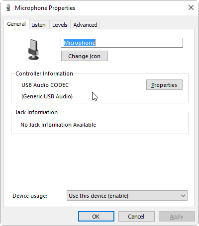
Select the "Levels" tab and set the level to as close to 0 dB as is available:
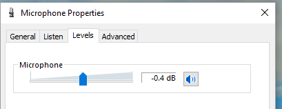
Then select the "Advanced" tab and change the type of converter.
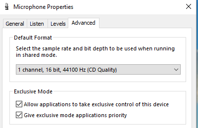
Apply and save the changes. The last step is usually needed to insure that the settings are not lost when the operating system is closed and restarted.
Transmit audio
Too often you see an overdriven signals on the digital sub-bands; multiple audio sidebands on PSK, splatter from overdriven MFSK and RTTY. There is absolutely no reason for a transceiver driven by fldigi to exhibit this type of performance. You can set up your computer / transceiver for good solid performance without excessive drive.
The "TUNE" button generates a continuous single frequency audio signal at the exact frequency to which the waterfall cursor has been set. The peak amplitude of this signal is the peak amplitude of every modem signal generated by fldigi. None will exceed this value, even the simultaneous multi-tone modes like Throb. Every modern SSB transmitter uses some automatic level control ALC for preventing overdrive for SSB voice. A little overdrive on a voice channel can be tolerated to a degree. In fact, that is what an analog RF compressor does, overdrive and then subsequent filtering. But you absolutely cannot tolerate that with the digital modes. Here is the way to set up your transceiver for a clean signal. I recommend starting out with a dummy load, but an "off hour" for a band might work just as well if you do not have a dummy load. If available, set the transceiver power level control for maximum power output. On my Icom 7100 and Yaesu FT991A that is 100 watts.
- Make sure your transceiver's speech compression control is OFF
- Set the operating system audio output mixer control to about 10% of full scale output.
- Set the fldigi transmit attenuator to -3 dB (control to the left of the AFC button)
- Set the waterfall cursor to 1000 Hz
- Enable the "Tune" mode in fldigi ... you do have CAT or PTT set up ...right?
-
Slowly bring up the Mixer audio output level until your rig's ALC just starts to function (a light blinking or a meter showing this condition).
That will probably be at about 30 watts output if the transceiver is rated at 100 watts. - Reduce the Mixer audio output until the ALC is disabled.
- You are now transmitting at maximum output power without distortion.
- You can use the fldigi transmit attenuator to make small adjustments in the output power to compensate for variations in the SSB transmit filter.
You can use any level below this and be assured that your output signal will be clean. All digital signals that fldigi generates will be limited to this peak-to-peak voltage. You should always use the minimum power necessary to maintain good comms, remember that even if you are clean at 100 W you signal will be so strong among the QRP signals that it will overpower the AGC on many receivers that are working another digital station within the same SSB bandwidth that you are on. You will appreciate this the first time that you are working a weak PSK DX station and someone blasts through and captures your AGC.
You should try the the above adjustments at different audio frequencies. Transceivers that achieve the SSB filtering with crystal or mechanical filters will have a considerable amount of variation across the passband of the filter. This will show up as a varying amount of ALC that is dependent on the audio frequency. Once you are comfortable with the process you can very quickly repeat the "Tune" and set the power for the frequency to which the waterfall is set. The fldigi transmit attenuator control should have sufficient range to compensate for transmit SSB filter variation. You do not want to transmit (or receive) near the cutoff frequencies of the SSB filter. The transceiver filter will introduce both phase and amplitude distortion over the signal bandwidth.