Table of Contents
PSM Configuration
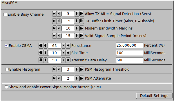
The Power Signal Monitor (PSM) configuration panel consist of four different sections. Each with specific functions to enhance the detections of signals with the intent of minimizing collisions.
- NOTE:
- In the event of a transmit with PSM enabled, the T/R button light will indicate yellow when a pending transmission is in play. Deselecting a second time (while yellow or red) will terminate the transmission.
Busy Channel

To enable Busy channel select "[x] Enable Busy Channel" checkbox option provided on the left hand side of the configuration panel.
There are a number of control parameters for adjusting to the current conditions.
Allow TX After Signal Detection (Seconds)
Places a TX inhibit any time there is a signal present on the waterfall. When a signal is detected the inhibit timer is reset to the selected value and will remain inhibited for the specified duration (minimum, in seconds). This can be useful during signal fades allowing for a period of time elapse to ensure the signal has completed. Generally it's a good idea to turn this option on when there is fair amount of QSB. This also can be used to prevent FLDIGI from transmitting in between the gaps of RSID and the data stream.
TX Buffer Flush Timer (Minutes, 0=Disable)
If there is an extended period of time when FLDIGI has not been allowed to transmit. The transmit buffer is cleared to prevent an excessively long transmit period once the frequency clears. This is generally not an issue with keyboard ops, but with programs using one of the three IO ports (ARQ/KISS/XMLRPC). It's possible large sums of data might be present in the transmit buffer.
Setting this value to 0 (zero) disables the TX buffer flushing.
Modem Bandwidth Margins
The method used to detect a signal is the difference between high and low values within in bandwith of the modem in addition to the bandwidth margins. If a modem is selected (like MT63) there is very little difference in the high/low values within the bandwidth of this modem. By extending the sampling to just outside of the modem bandwidth high/low values are typically present. However, the draw back to extending the bandwidth margins is nearby signals will effectively keep FLDIGI from transmitting until both the margin and modem bandwidths are clear.
Valid Signal Sample Period (Milliseconds)
As a general rule, the shorter the sampling period the better. The actual sample rate has as much to do the the Waterfall display rate. PSM is event driven by the waterfall update routines. Ensure the Waterfall display rate is set to "FAST" for best results.
Carrier Sense Multiple Access (CSMA)
Carrier Sense Multiple Access CSMA adds a little randomness to the transmit process. By varying the transmitting actions of FLDIDI by random amounts synchronized transit collision can be reduced.
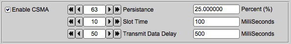
To enable CSMA select "[x] Enable CSMA" checkbox option provided on the left hand side of the configuration panel.
Persistance
Persistance is the random part of the process. A random number is generated and compared to the persistance value. If the persistance value is lower then the generated number tranmission is allowed. The second field in the Persistance row (config panel) indicates the percent chance of transmitting each time a random number is generated and compared. The accumulative delay in the transmit period is governed by the slot time.
Slot Time
Slot time is the minimum amount of time between data transmissions of open air time. No transmissions are allowed during this break. This variable effects the delay period as governed by the persistance parameter. The persistence value prevents the transmission and is delayed by the slot time value before the persistance value can be evaluated again during the random number generator and compare process.
Transmit Data Delay
If the modem being used has the option to idle transmit. This is the duration in milliseconds the transmissions send idle data. Useful for repeaters or other conditions that have a delay before decoding can occur.
Histogram

This option is experimental. The basic idea is to keep the PSM threshold a few points just above the noise level. If the noise level changes so does the histogram reference. It's intended to be used with FM modulations. This option is not suitable with Busy channel.
PSM Attenuation (Sensitivity Adjustment)

Generally you would want to keep the value around 2 to 4 for over the air use. If you are testing using a direct connect (soundcard to soundcard) you will need to increase the attenuations up considerably. The representation of the value is simply a 1 over N fraction. If the attenuation value is set to 2 then the attenuation is 1/2 of the full signal level.
Enable PSM Use on Front Panel.

Selecting this checkbox enables the PSM button on FLDIGI's main window.
Resetting PSM to Defaults.
Pretty simple, just press the [ Defaults Settings ] button.