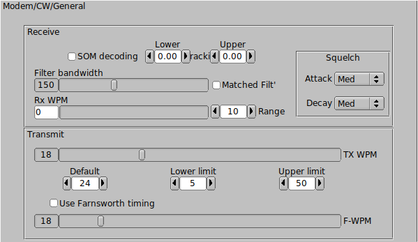
Fldigi can send and receive morse code from 5 wpm to 200 wpm. The operating controls for CW are found on the Config/CW tab. You can open that tab by selecting the "Configure/Modems" menu item and the clicking on the Modems/CW tab. You can also open up the CW tab by first selecting CW as the operating mode and then clicking on the left-most item "CW" on the status bar at the bottom of the fldigi main window. During operation the Rx and Tx WPM settings are annunciated on the status bar in the two boxes next to the mode indicator.
The CW signals are converted to a baseband signal. It is the digital equivalent of tuning an analog USB transceiver so that the carrier is exactly at the CW carrier frequency. The CW decoder uses a Fast Fourier Transform (FFT) filter implemented with a sin(x)/x impulse response. This is a very steep sided low pass filter. The FFT filter is optimum when receiving CW in a white noise environment. Select "Matched" filter to optimize the filter width for the current transmit WPM setting. A lot of impuse noise (static) can cause the filter to ring. Increasing the filter bandwidth might improve detection in that QRN environment.
Fldigi can track the incoming signal. Enable Rx WPM tracking by enabling the check box "Enable Tx Trkg". The tracking range (+/- Hz around the TxWPM setting) can be set using the "Rx Trkg Rng" control. When tracking is enabled the tracking filter is reset every time the transmit WPM is adjusted.
CW detection is basically an amplitude demodulator with an automatic threshold adjustment.
You can control the attack and decay squelch parameters of the detector, slow - medium - fast, for both attack and decay.
The RxWPM control is an indicator and is not used for setting the operation of the CW decoder.
"SOM decoding" provides a fuzzy logic implementation to match the RX stream detected on-off sequence to a "best fit" character. It can increase the probability of correctly identifying the text character under very noisy conditions.
The TxWPM sliding controller is used to set the transmit WPM. To make the setting easier two additional controls are provided. "Lower" sets the lower limit of the slider and "Upper" sets the upper limit of the slider. The resolution of the TxWPM slider is 1 WPM. The Lower/Upper controls are in in 5 WPM increments.
The transmit encoder settings for WPM can also be adjusted with three hot keys:
- Numeric keypad "+" increases the TxWPM by 1
- Numeric keypad "-" decreases the TxWPM by 1
- Numeric keypad "*" toggles between the selected TxWPM and a default WPM
The "Default" control on the CW tab sets that default value. As shown above the TxWPM is 30 and the default is 18. If during a QSO you needed to slow down to give the other op a better chance to copy what you are sending, just hit the "*" on the numeric keypad and the CW code will immediately switch to sending CW at the set default value (18 wpm in this example). Press the "*" again to return to back to the CW speed that you were previously using.
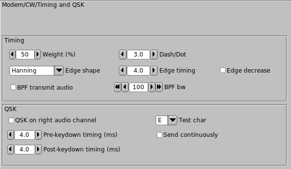
Timing
Fldigi generates CW by inserting a keyed tone at the current waterfall audio frequency. The transceiver should be operated in either USB (preferred) or LSB mode. The CW signal is completely generated in the software so it is possible to control many aspects of the CW signal. The actual transmitted signal will be at the USB carrier + the audio frequency, or the LSB carrier - the audio frequency. If fldigi is tracking and receiving a CW signal on the waterfall your transmitted signal will be exactly on the frequency of the other operator. The CW generated this way has a nearly ideal attack and decay time, controlled by the software modem. But ... a caveat ... your transmitter must never be overdriven and it should have excellent opposite sideband suppression. Overdriving the transmitter can cause multiple audio signals within the SSB passband, and cause unwanted interference to other ops. The same is true for a poorly designed or adjusted transmitter with bad sideband suppression. I recommend having a trusted and knowledgable operator assist you when first trying A2 CW. Have them carefully look for evidence of your signal above and below your primary signal (by at least +/- 3 Khz). If there is no evidence of extra signals then your are set to go. If there is you might want to have the transceiver adusted for sideband suppression, or check to be sure you are not over driving the audio.
-
Wt % control sets the weight of the CW. Normal CW is at 50% weight, ie: a dot is equal to the interval between dots or between code elements. It has a range of 20 to 80 percent.
-
Dash/Dot controls the relative weight between a dash and a dot. The standard for CW is 3 to 1. The dash is 3 times the length of a dot. Some operators prefer the sound of either a heavier or lighter sounding CW. This control can be adjusted from 2.5 to 4.0 in 0.1 increments.
-
Edge shape provides two leading/trailing edge shapes (1) Hanning, or raised cosine, and (2) Blackman a modified raised cosine with a steeper attack and decay. Both of these edge shapes give a more narrow bandwidth CW signal than the traditional exponential waveform. They are very easy to listen to even at speeds exceeding 100 wpm.
-
The Edge control sets the rise and fall times of the CW waveform. It can be set anywhere from 0.0 to 15.0 milliseconds in 0.1 millisecond increments. DO NOT operate A2 CW with the control set below 4 msec. This is the control that sets the effective bandwidth and sound of your CW. If the edge is too steep you will have a clicky signal and be the bane of the CW bands. The purpose of being able to set the edge to 0.0 or a very quick rise/fall time is explained below. A good setting for nice sounding CW at 40 WPM and below is 4 to 6 milliseconds.
-
Edge decreases pulse width, when checked will give a slightly narrower dot length as the edge timing is increased. This is useful when operating QSK and listening between the character elements.
- The transmitted signal can be further wave shaped using a "Windowed-sinc" bandpass filter. It is enabled by checking the "BPF transmit audio" check box. The bandwidth of the filter can be adjusted from 10 to 1000 Hertz with the BPF bw control. The filter will always be centered on the AFCW injection frequency (waterfall TX cursor position). You should both visually observe and listen to the resulting CW signal. The easiest way to do this is to enable the "Send continuously", select a test character and then press the TX button on the main dialog. The weight, dash/dot, edge shape selection, edge timing, BPF and bandwidth can be changed with immediate effect.
This is what the A2 signal should look like with various settings of weight, Dash/Dot and Edge. The audio frequency is 400 Hz and the TxWPM is 100 WPM.
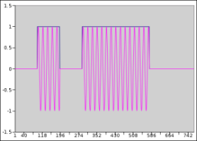
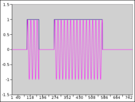
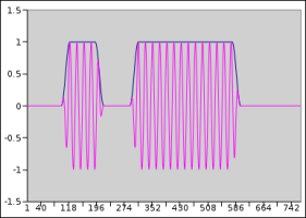
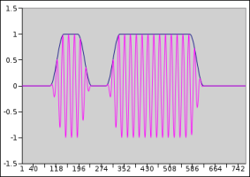
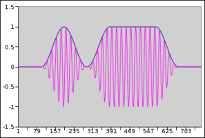
Changing the weight, dash/dot or edge of the waveform does not change the WPM at which the code is generated. When a conflict occurs between the various settings WPM takes first priority, and Edge second. In the above examples, the Edge setting could not exceed 12 msec even if the control were set higher than 12.0. The figures were generated by capturing the output data being sent to the sound card and then formatting it using Gnumeric. An oscilloscope photo of the signal is virtually identical.
The setting for inter-character and inter-word spacings are fixed at 3 and 7 respectively. The 3 is achieved by sending a silent period of 1 dot (element) length at the beginning of each character and 2 at the end of each character (shown in the figures). This silent period is sufficient for most transceivers to respond to the PTT signal which occurs at the beginning of the transmission so that the first dit or dash is not lost in transmission.QRQ (high speed CW operation)
You may wonder why fldigi can go as high as 200 WPM. It's hard to believe but there are CW operators who can decode 100+ WPM in their head. These operators also usually operate QSK (full breakin). A2 CW and PTT operation and QRQ/QSK are not a natural mix. But fldigi can be used for this type of operation if an external keyer is used. For that purpose the A2 Tx output from fldigi is full wave rectified and detected to create a keyline control. The outboard conversion from A2 to keyline requires a nearly square wave pulse output of audio at the CW keying rate. Setting the Edge control to 0.0 and then the audio frequency to about 1000 Hz provides the needed signal to effect this type of keyline control.
If you are operating QSK with a separate receiver / transmitter you can very quickly stop your transmit signal with the TAB key. In the CW mode only the TAB key causes the program to skip over the remaining text in the transmit text buffer. The text that is skipped will be color coded blue. The program remains in the transmit mode (PTT enabled), but since the buffer is now empty no A2 CW signal is generated. Code transmission will then restart with the very next keyboard closure of a valid CW character. The Escape and Pause/Break keys still can be used to respectively abort and pause transmission.
QSK
Many QSK operators use high speed diode antenna switching between receiver and antenna. fldigi generates a signal that can be used for that purpose. The left audio channel is always theAFCW signal. When selected the right audio channel can be configured to generate a square wave signal that begins earlier and ends later than each of the CW elements. The square wave signal can be rectified and filtered to provide the diode switching signal for the Rx/Tx antenna switching.
The right audio channel QSK signal is selected by checking the box and then adjusting the pre and post timing in millisecond increments. Additional information and a schematic diagram of a QSK keying circuit is described in CW Keying. Setting up a QSK device can be quite difficult. Fldigi helps to ease the adjustment by generating a continuous series of characters. This allows a dual trace scope to be properly synched while making the adjustments to both the software and the associated QSK hardware. You enable continuous characters by selecting the checkbox, and then enabling the T/R button for transmit. The repeated character can be change on the fly with the pick control. It can be one of either E, I, S, T, M, O or V.
PROSIGNS
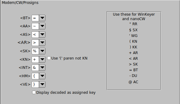
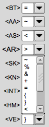
You can assign keyboard characters to be used for Morse prosigns. The available characters are: ~ % & + = { } < > [ ]
The default assignments are shown above. You can also elect to send and receive the KN prosign as an open parenthesis '('. This is commonly used on MARS CW operations.
See Operating CW for additional information.
See nanoIO Interface for additional information on nanoIO interface.
See WinKeyer Interface for additional information on WinKeyer interface.
See CW Keyline Configuration for additional information on DTR/RTS keying.
See CW CAT Keying Configuration for additional information on CAT keying.
Return to Top of Page
Return to Main Page