Table of Contents
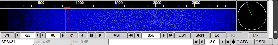
The main display for fldigi is the waterfall display shown above in color and in scale x1.
The button WF toggles the display between a waterfall, a spectrum display and an oscilloscope type view of the Rx and Tx signals. This button acts as a rotary. Left clicking moves the display selection in one direction and right clicking in the other direction. The three display modes are WF - waterfall, FFT - spectrum (Fast Fourier Transform) and Sig - oscilloscope time domain. Let the mouse cursor hover over any one of the controls and a small hint box will open to help you navigate the various controls.
The Norm button controls the speed of the waterfall drop. This is also a rotary type of button control. The speeds available are SLOW, NORM, FAST and PAUSE. The load on the cpu will be directly proportional to this selection. If your cpu is slow you might want to select the SLOW or PAUSE option for the waterfall.
The scale control (X1, X2, X4) expands or contracts the view into the fast fourier transform that is displayed on the waterfall or the FFT display. fldigi always computes the FFT to a 1 Hz resolution, and displays the results according to the scale control.
The next three controls are positional conrols for the waterfall. The waterfall can display 4096 data points, where each one can be thought of as a spectral line at the equivalent Hertz. The ratio is actually 8000/8192 and is related to the ratio of sound card sampling rate to Fast Fourier Transform length. This ratio changes for some modems that require a sampling rate other than 8000 Hz. The left arrow key will shift the display to the right (displays a lower section of the spectrum). The right arrow key moves the display higher in frequency. These two buttons are repeating buttons. Hold them down and the display slews at about 20 shifts / sec. The center button with the two vertical block lines is a "center the signal" button. The current cursor (red signal cursor in the waterfall) will be centered in the display area.
NOTE: these controls are only functional if the current waterfall or spectrum view is smaller than the full view available. This is usually the case when the X2 or X4 expansion is selected. But it also might be the case when the width of the main dialog is reduced so that the waterfall display does not extend over the entire available width.
Try moving the cursor around in the waterfall area. You will see a set of yellow cursor blocks that show the center point and bandwidth of the current operating mode (psk31 = 31.25 Hz for example). To capture a received signal just click near the signal and the AFC will perform a multi-step acquisition. This will be very fast and should not require additional operator intervention. Casual tuning You can take a look at any received signal on the waterfall by right-clicking and holding the mouse button on or near the signal. The modem will begin to decode that signal if it is in the currently selected mode. The text will be a unique color on the Rx text widget so that you can discern the difference between casual and normal tracking. Release the mouse button and the tracking returns to the previously selected normal tracking point.
Audio History Fldigi maintains a history buffer of the received audio. This buffer is approximately 2 minutes in duration. After tracking commences on a signal you can decode the audio history for that signal. The audio history is invoked by a Ctrl-Left click anywhere on the waterfall. You can also invoke the audio history for the casual tuning mode by pressing Ctrl-Right click on the waterfall.
The next control is your transceive audio frequency. In the display above you can see that the audio signal is 1500 Hz. The red cursor is centered beneath 14071.500 Mhz. The transceiver was set to 14070 Mhz. The arrow key pairs move up/down in cycles and tens of cycles. You can fine tune the receive point using this control.
The next two controls to the right of the audio frequency control are for the receive signal processing. The one that reads -10 is the max signal level for the waterfall/spectrum display. The one that reads 51 is for the range over which that control will display signals. Both of these are in dB. The default of -10 / 40 is a good starting point, but you need to adjust these for band conditions. You can see the impact of these controls most easily by putting the main display area in the spectrum mode. Changes in these controls will effect the waterfall instantly and for all past history displayed on the waterfall. You do not have to wait for new signal data to observe the affect.
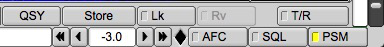
The QSY button is very specific to transceivers interfaced with either hamlib, rigcat or when fldigi is used with flrig. Each transceiver has a sweet spot associated with its bandwidth controller. For the FT950 is 1500 when the transceiver is set to PKT-U. As the transceivers bandwidth is changed the changes occur centered at this frequency. Set the "Sweet spot" frequency (Config / Misc / Sweet Spot) to 1500. Let's say that I just started copying a rare dx at 1758 Hz and I wanted to put the signal at the sweet spot so I could easily narrow the receiver bandwidth. Click on the signal on the waterfall. Let the AFC capture and then press the QSY button. The tranceiver frequency will be shifted and the fldigi audio tracking point shifted in unison such that the signal is now at the receivers sweet spot. Very fast and very convenient! The QSY button will be dimmed and not activated if you do not have a method of transceiver control enabled for your transceiver. Right click on the QSY button to undo the action.
This can also be achieved with the <QSYTO> and <QSYFM> macro tags. If you combine these two with the <FILWID:nnn> command you can center the signal in the passband and also narrow the transceiver passband, i.e. when used with the FT950
- <QSYTO><FILWID:200>
- <QSYFM><FILWID:2400>
The Store button allows you to store, recall and manage mode/frequency pairs. If you want to save the current mode and frequency simply left click the button. A right click will enable a popup menu from which you can select a previously stored set. You can quickly move between modes and audio sub carrier using this technique. A shift-left click will clear the memory. When the popup menu is visible you left click on an entry to select it. You can shift-left click on an entry to delete that single entry.
The T/R button should be self-explanatory. It's your transmit/receive button. Action is immediate, so if you were transmiting some text and hit the button the PTT is disabled, the transmit text area cleared and the program returned to receive mode. The T/R button is a "lighted button" that shows when transmitting. All other lighted buttons show YELLOW when they are in the active state.
The Lck button locks the transmit audio frequency to its present value. You can then continue to QSY around your transmit position. I have used this to reply to a DX station that wanted a +500 Hz response. The DX was at 690 Hz audio, and wanted a response at +500. I moved the display cursor (or the audio frequency control) to 1190 Hz. Hit the Lck button and then went back to 690 with the waterfall cursor. Now the program is receiving on 690 Hz and transmitting on 1190 Hz. Caught him on the first try. Use this button also as a Master Station control. Not all rigs are equal in their VFO performance. Some exhibit a shift between receive and transmit. If this occurs then the stations find themselves chasing each other with every t/r exchange. Locking your transmit frequency with this control will inhibit that from happening. Be sure to disable the control when that qso is over or you may forget and transmit over top of another qso!
If the "Lck" is enabled the TX frequency does not follow the AFC action applied to the RX frequency.
For transceivers which are either hamlib or memmap enabled, if the "Qsy" button is pressed BOTH the RX and TX frequencies are changed to synchronize to where the RX was positioned.
Perhaps some numbers will help to make that a little clearer.
| "Lck" | Before "Qsy" | After "Qsy" | ||
|---|---|---|---|---|
| RX | TX | RX | TX | |
| OFF | 1002 / 7071.002 | 1002 / 7071.002 | 1500 / 7071.002 | 1500 / 7071.002 |
| ON | 1002 / 7071.002 | 1000 / 7071.000 | 1500 / 7071.002 | 1500 / 7071.002 |
| ON | 1000 / 7071.000 | 1800 / 7071.800 | 1500 / 7071.000 | 1500 / 7071.000 |
With "Lk" off the TX audio frequency is always synchronized with the RX frequency.
With "Lk" on the TX audio frequency is fixed with respect to the RX frequency UNLESS the "Qsy" button is pressed in which case it shifts to the RX frequency, the Transceiver VFO is shifted and both the RX and TX audio frequencies are shifted to put both into the middle of the transceiver passband. The TX continues to be locked, but at the new audio frequency.
If the "Lk" is ON moving the cursor around will ONLY AFFECT the RX frequency and NOT the TX frequency.
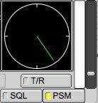
The AFC and SQL buttons enable or disable the respective function in the software. The slider just above the AFC & SQL controls is the squelch level control. The bar indicator just above it is the equivalent of received signal level and relates on a 1:1 basis with the squelch level slider. The SQL button illuminates YELLOW when the SQL is selected, but the signal is below the squelch level. It illuminates GREEN when the the SQL is selected and the signal is above the squelch level.
The indicator just to the left of the AFC button is the overload indicator. It will be GREEN if your audio drive to sound card is satisfactory, YELLOW if the audio signal is marginally high and turn red when it is in overload. Back down the mixer control or the audio pad from the rig to computer. Fldigi will not perform well if the sound card is over driven. You will see ghost signals on the waterfall and the modem decoders will not work correctly.
PSM operates on the power aspect of a signal unlike SQL which measures the reception quality of the signal. For PSM to operate correctly the waterfall speed setting must set to FAST. The level setting slider is active for PSM when the PSM button is enabled (indicated by either a yellow or green square on the button surface). When disabled the slider adjustment effects SQL. With PSM button selected the user sets the threshold using the slider to the right of the vertical level indicator.
SQL and PSM functional differences:
SQL - Inhibits character reception.
PSM - Inhibits the data transfer to the modem modulator.
Receive audio level should be adjusted so that the overload indicator does not illuminate red. When observing the received signals on the oscilloscope view you should expect that they do not exceed a peak-to-peak amplitude of 3/4 of the full display height.
Mode Status Indicators
The lower left corner of the main display (MFSK-16) in the view above is actually a button disquised as a status panel. This button responds to the mouse in several ways:
- Left Click - opens a quick pick list of associated modem types; you can switch to a new modem type from this popup menu
- Right Click - opens the configuration dialog at the tab associated with the current modem type
- Scroll Wheel - rotates forward and backwards through the various modem types in accordance with the modem menu heirarchy. Stop at the one you want and you are now in that mode
The next status indicator to the right provides information relative to the current modem, for PSK it indicates the received signal strength in dB.
The third status indicator from the left provides additional information relative to the current modem, IMD for PSK measured in dB.
Note that for PSK these values are only measured during periods when the PSK idle signal is being received.
Transmit level attenuator
It is often difficult to adjust the audio drive for the point where ALC is just barely active. Mixer controls are OK, but not usually designed for very small changes. They are after all designed for adjusting listening levels. fldigi provides the ability to control the audio drive in increments of 0.1 dB over a 30 dB range. This control is located in the bottom right corner of the main dialog:
Set this control for -6 dB and then adjust the sound card mixer control for the best ALC level you can achieve. Then adjust the Tx-level control for best "just visible" ALC on the transceiver. That should give you a very clean PSK signal.
Operating split with fldigi / flrig
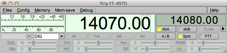
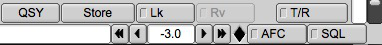
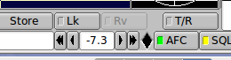
Note: In the above example most features are disable as they are not available for the indicated radio.
On flrig:
Unless specifically supported by the transceiver and implemented in flrig.
- VFO A is always the RX frequency.
- VFO B is always the TX frequency.
- Left Click on the A/B swaps A & B VFO frequencies.
- Right Click on the A/B assignes A VFO frequency to B VFO.
- Using the mouse wheel adjust VFO B to where you want to transmit.
- Click the SPLIT button, it will change color when it is active.
- Press the VFO B button to listen on the Tx frequency, be sure to press Split again before capturing that rare DX station.
On fldigi:
- Tune the waterfall cursor to the Rx signal
- Transmit as usual, be sure you are not doubling.
See FLRIG Help for specific operating procedures.
Some additional information can also be found here Rig Control Page